Design
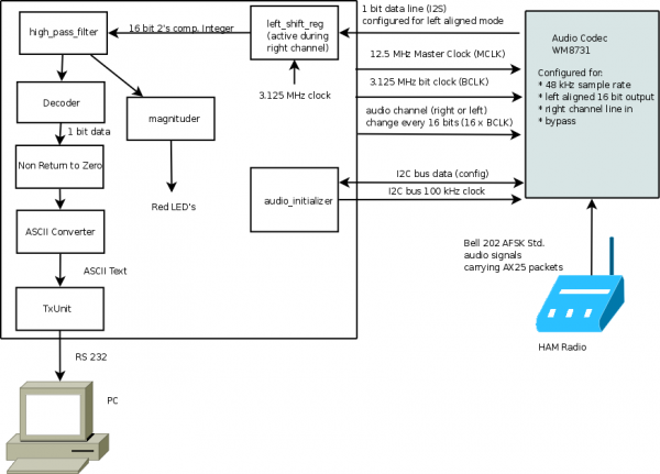
The final design of the system consists of a component to initialize the audio, components to read the single-wire audio data and send it through a filter. Then a component to decode the audio signal into binary data will pass through the trivial NRZ-encoding component and finally convert it to ASCII. Then this ASCII text can be sent through the serial port and read or logged on a PC. An additional component, the "magnituder", was added to make this project more visual in the absence of some of the other connecting pieces.
Configuring Audio Codec
Configuration of the audio codec is done using the I2C bus. The default state of the audio codec has all its outputs turned off, bypass mode enabled, and the line and and microphone inputs muted. We had to turn line in on, configure the audio path to sample line in on the analog to digital converter, and set the format of data for the chip to send out over its I2S bus.
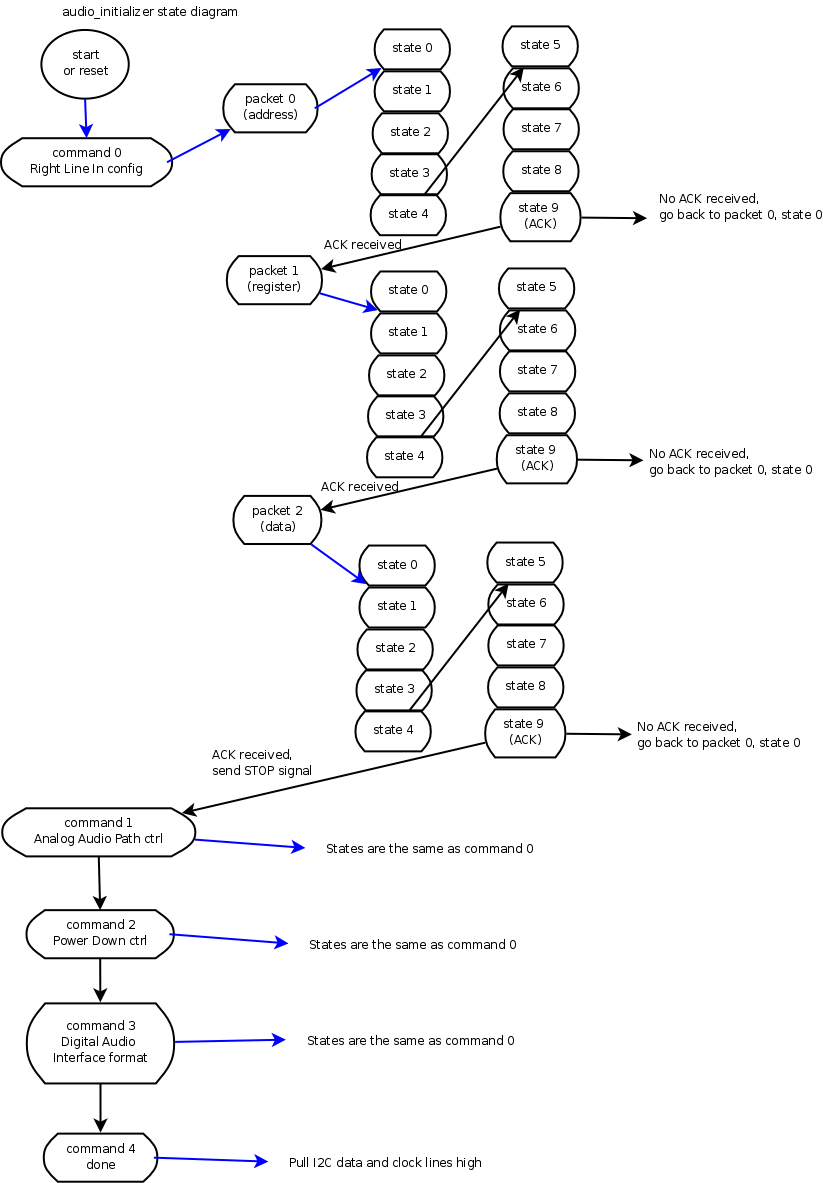
Each register was configured by sending a START signal, the address of the audio codec, the R/W bit, read an ACK signal, the address of the register, read and ACK signal, the register data, read an ACK signal, and the STOP signal. One sequence of these events corresponds to a "command" in the state machine. Each 8 bits sent between ACK signals corresponds to a "packet" in the state machine, and each bit corresponds to a "state" in the state machine.
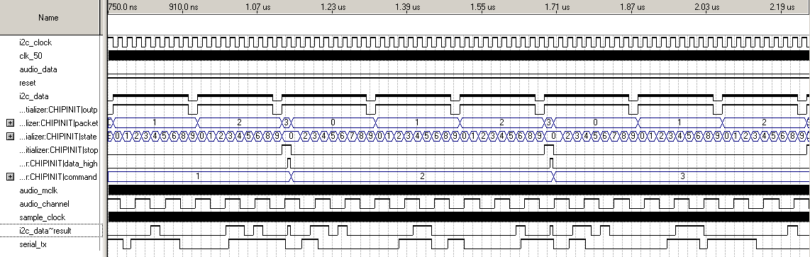
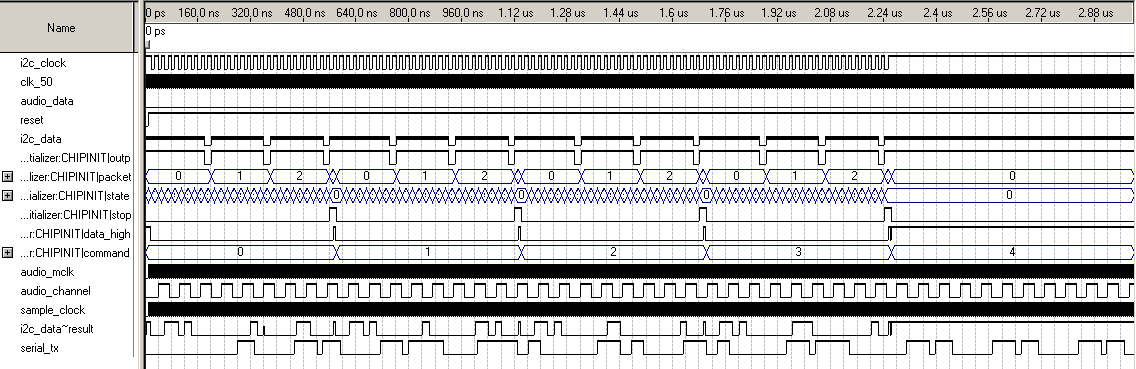
You can see the different states the audio_initializer goes through in these simulation waveforms. Once the initialization is done, the STOP signal is given for a final time and the data and clock lines for the I2C bus are pulled high. If the reset button on the board is pressed, the configuration will be successfully run through again. Since the I2C data line is bidirectional over a single wire, we needed to read the ACK bits over that wire. During simulation this meant adjusting the data line quite precisely so the input was there when the state machine expected it. If we were off there would be logic contentions the simulator could not handle or unknown values the simulator could not handle.
The line labeled i2c_data is actually the input of the bidirectional line, most of the time it is at logic Z (unkown). The simulator also generates the result, called i2c_data~result in the waveform. If the input from i2c_data (which we edited by hand) and the times when it is trying to output to the line overlap at all, there will be a logic contention. The input or output state of this line is controlled by a tri-state buffer. In code this means a value of 'Z' is written to the line when you want to read from it.
Handling Audio Data
Once the audio codec is properly configured, the data can be read on the ADCDAT line. With the configuration outlined above, 16-bits of audio data is provided in the left-justified mode at a rate of 48 kHz. To make this audio data readily available to other components in our design, we implemented a 16-bit shift register that runs on the ADCLRC signal reading only the the right channel audio data.
From SignalTap analysis, we noticed when no sound was coming into the system we would get small integer values off the data line from the audio codec, usually between about -6 and 6. This would occur even on the muted channel. This caused some confusion because when we output the raw integers to the 16 LED's the lights always appeared to be lit. This was because those integers were 2's compliment, so small negative values (which it was getting frequently as noise) were almost all 1's. I implemented a high pass filter to remove these values and our outputs worked quite well as a result. It is important to note the high pass filter works on the absolute value of the integers.
Decoding Audio
The design for the audio decoder is based on the premise of counting audio samples. Sampling audio at 48kHz, we conclude that we should receive approximately 40 samples per period during the 1.2kHz space tone, and approximately 17 samples per period during the 1.2kHz mark tone. The actual implementation resets thes sample count at zero-crossings (sign changes), so a threshold of 15 samples is uses. If less than 15 samples are taken since the last zero-crossing, we assume that we are in a mark tone, otherwise in a space tone.
The key to make this work is determining the clock that corresponds to each bit of data. Given a bit rate of 1200 bps and the space and mark frequencies described above, we can conclude that 1 period of space tone or two periods of mark tone correspond to a single bit. Thus we can create a reasonably accurate clock for the output data by essentially inverting the clock on every zero-crossing of a space tone and every other zero-crossing of a mark tone.
The real challenge to the decoding component is testing it. Simulating 16-bit audio samples modulate between 1.2kHz and 2.4kHz is not an intuitive task. Rather than trying to simulate such a complex signal, we creating a 16-bit signal where the sign-bit works like a clock, and the remaining bits are set randomly. While not a good representation of an audio signal, it suffices to trigger the logic that detects zero-crossings. Then, instead of trying to manipulate the audio signal input, the simulation is run using a different threshold to emulate the opposite tone.
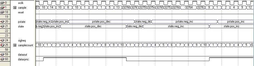
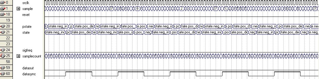
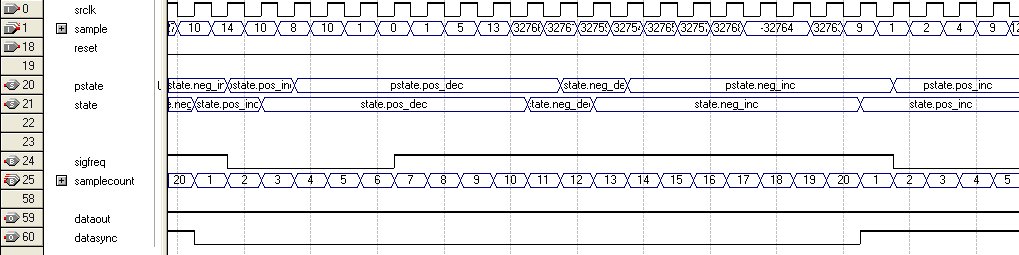
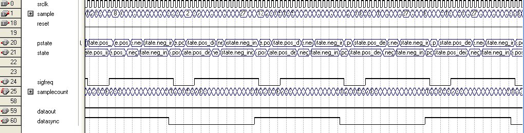
The waveforms below characterize the funcionality of the decoding component. The first 2 waveforms roughly reflect a space tone, where the data output is low and the generated clock is toggled at every zero-crossing. The last 2 waveforms corresond to a mark tone, where the data output is high and the corresponding clock is toggled at every other zero-crossing.
Despite these promising results, the decoder was not completed with sufficient time to integrate it into the complete system, adequately test it, and debug any issues that may arise using the DE2 hardware. Additionally the UART component is not ready to send this data to a PC, so visualizing the ASCII interpretation is not ready.
Audio Visualization
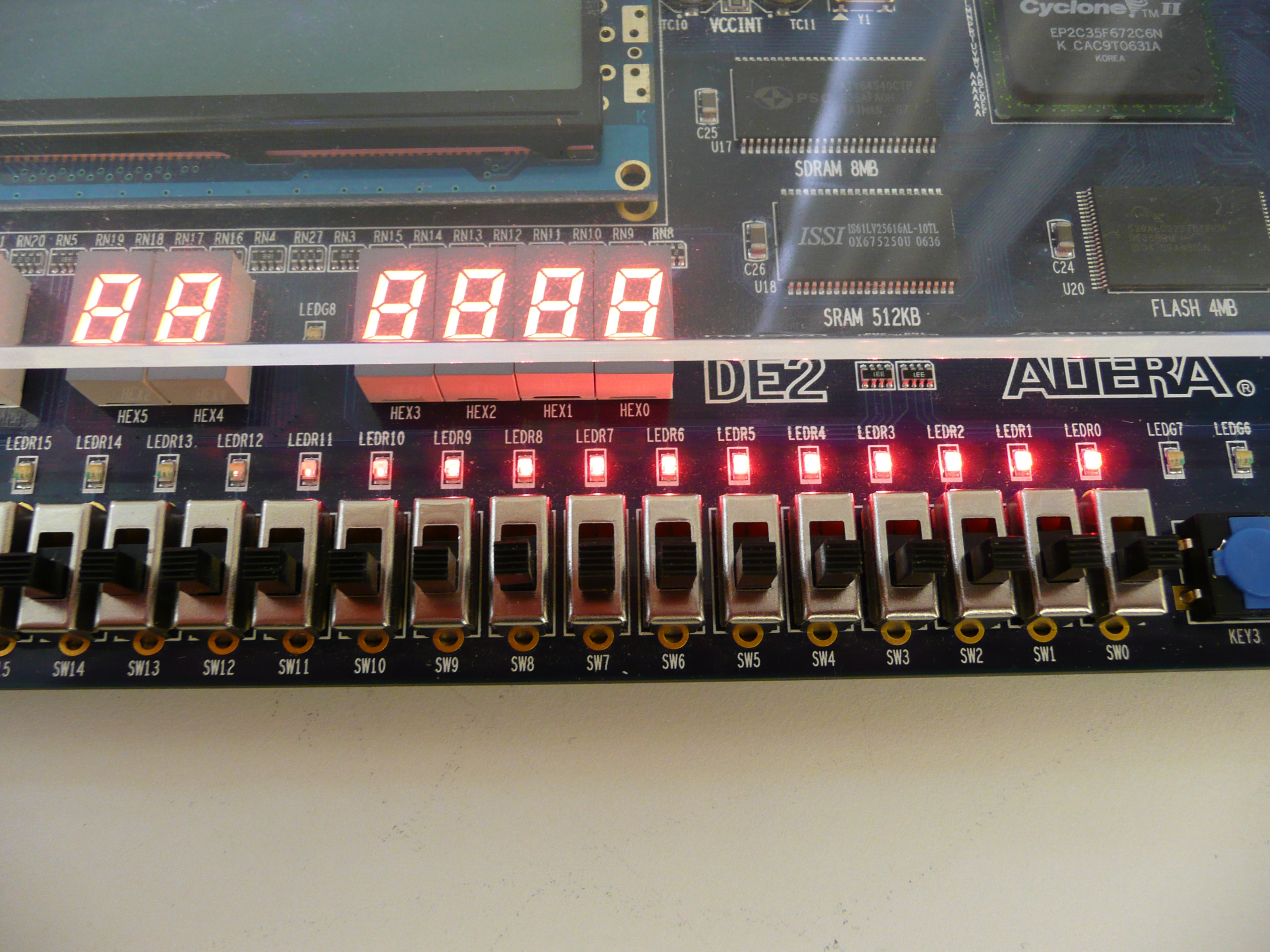
In the absence of a fully complete signal decoder and UART, and with the deadline looming near, I decided to implement a component that would allow us to visualize sound in a more impressive manner than our debug outputs. This insured we would have something to demo besides waveforms and output from the Signaltap analyzer. I fed the 16 bit 2's compliment integers from the high pass filter into this component, then found the absolute values of those integers. Since the integers from the audio codec represent the amplitude of the sound wave, I could use the magnitude of the integer to determine how many of the LED's to light up, producing a sound level indicator like that typically found on a stereo system. This component now provides the visualization for any sound input to the board. We found Queen's Bohemian Rhapsody song to be an effective demonstration of this output due to the large variety of soft and loud parts in the song. I like ACDC better, although their visualization has much less variety.
