Audio Configuration Difficulties
It turned out we needed to configure the Audio Codec before we could capture any sound data. This proved to be fairly difficult. The configuration of the Audio Codec was done over an I2C bus, which consists of a clock and data line.
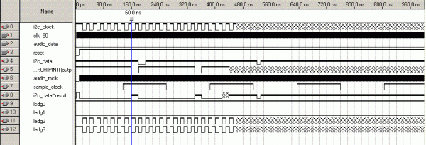
The chip expects a START signal, where the data line is pulled low, then the clock line is pulled low at least 600 ns later. The 7 bit address of the chip is sent, and 1 bit signifying read or write. After every 8 bits sent you must read the line for an ACK signal. After sending 16 bits of data you must send a STOP condition (opposite of a start condition) and start a new transmission. I had some difficulties simulating this system, if the data line was not edited during the ACK portion down to the nanosecond the simulator would not know what to do and put in hash marks for the rest of the waveform. This unknown state occured even though there was an else statement, the simulator would simply not have any idea what the value should be. Since the ACK placement depended on wavaform results, I had to run the simulation and then edit it in a repeating cycle to get the ACK sections accurate enough to work.
Audio Decoder Difficulties
The audio decoder portion of the system suffered from several setbacks. For starters, we needed to develop an algorithm for decoding an audio signal. Of course, this would be best served after having a characterization of the data being received. Since the process of configuring audio suffered several setbacks, the audio decoder was 'blindly' designed, assuming certain characteristics of the data that we would receive.
With regard to the design of the decoder, the lack of a signal to indicate start of each data bit means that the decoder had the added responsibility of determining which samples indicated the start/stop of each bit in the AFSK-encoded message. The state machine design for this suffered from a complication that led to successful compilations but simulations that would halt half-way through simulation based on certain characteristics of the input data. Several redesigns of the logic were implemented until this issue was finally resolved.
However, even at this point, there was no "audio signal" or real audio samples to use as the input for testing. Therefore, the large majority of waveform analysis of the decoder was based on the idea of using a signal that flipped the sign bit with respect to the frequency, and randomized many of the other bits. While this input is not a very good characterization of an audio signal, it was enough to implement logic that attempts to detect "zero-crossings" in the input samples and use that as the basis for determining frequency.
Once the signal decoder was functionally complete (as far as could be deduced from waveform testing), it was far too late to successfully integrate, test, and debug in the rest of the system. The realization of this a few days prior is what led to the creation of the LED-based visualization components.

